Method for measuring fatigue life of thin film constrained by flexible substrate
Technical Field
The invention relates to the technical field of fatigue performance tests of thin film materials, in particular to a method for measuring fatigue life of a thin film constrained by a flexible substrate.
Background
Metallic or non-metallic thin films with substrate support are widely used for interconnect line or electrode structures in microelectronic devices. In particular, in recent years, the rapid development of flexible electronic devices has led to a great deal of attention being paid to the mechanical properties of thin films on deformable flexible substrates. When the device is repeatedly deformed by stretching, bending, twisting, or the like, the film material is inevitably subjected to cyclic load, and further fatigue damage or failure occurs. However, the experimental method for fatigue damage of thin film materials is not complete, and currently, the critical fatigue failure frequency of the materials is generally determined by measuring the physical parameter change (such as the rigidity change or the resistance change of the sample) of the sample. These methods have the disadvantages of difficult sample preparation, complicated experimental process, etc., and are not suitable for testing non-conductive non-metallic films. Therefore, it is necessary to develop a universal fatigue test method for thin film materials to simply and effectively evaluate the fatigue performance of metal or non-metal thin films and determine the fatigue life thereof.
Disclosure of Invention
Aiming at the problem of how to determine the fatigue life of a metal and non-metal film constrained by a flexible substrate, the invention aims to provide a method for measuring the fatigue life of the film constrained by the flexible substrate, which introduces cyclic tension-compression strain in the film through repeated bending fatigue loading, and is similar to the traditional tension-compression fatigue test of a bulk material. Meanwhile, the method is easy to operate, the sample preparation is simple, and a series of critical fatigue failure strains epsilon under different loading cycles N can be obtainedcI.e. corresponding to the strain amplitude εcThe fatigue life of the film under load was N weeks. Obtained epsiloncAnd the-N curve is a film fatigue strain amplitude-life curve. The method provides a new idea for evaluating the fatigue performance of the flexible matrix film.
In order to achieve the purpose, the technical scheme adopted by the invention is as follows:
a method for measuring fatigue life of a thin film constrained by a flexible substrate, the method comprising the steps of:
(1) preparing a film on a flexible substrate into a fatigue test sample;
(2) carrying out strain calibration on a fatigue sample under certain deflection;
(3) performing a bending fatigue test on the fatigue sample under the same deflection, and stopping the test at a fixed cycle N;
(4) and determining the critical fatigue failure strain corresponding to the farthest crack position of the fatigue test sample under the fixed cycle loading. I.e., equivalent to a fatigue life of the film of N cycles under this strain loading.
In the step (1), the preparation process of the fatigue sample comprises the following steps: the film is prepared on a flexible substrate to obtain a film-substrate composite material, and then the film-substrate composite material is cut into a rectangular fatigue sample.
In the step (2), the process of performing strain calibration includes: firstly, applying a certain deflection to a fatigue sample by using a strain calibration device to enable the sample to be bent and deformed; and then acquiring an image of the cross section profile of the sample and fitting a cubic polynomial to the profile curve to obtain a fitting equation y (x), wherein the origin of coordinates is established at the clamping root of the sample, x is the distance between each point and the y axis when the sample is bent, and y is the applied deflection. By the theory of the elastic beam, the external strain epsilon of each point along the length direction of the fatigue sample can be theoretically calculated when the fatigue sample is bent; strain epsilon is h/2R, wherein h is the total thickness of the film-matrix composite material, and R is the curvature radius of each point when the point is bent; the radius of curvature R can be represented by the formula
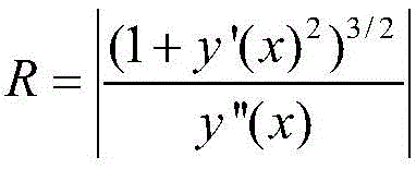
Obtaining; the strain maximum occurs at the clamping root and gradually decreases along the length of the fatigue specimen.
In the step (3), the bending fatigue test is implemented on a cantilever beam dynamic bending fatigue device, one end of the sample is fixed, and the other end of the sample is loaded by adopting calibrated deflection; cyclic loading is achieved by reciprocating vibration of an electromagnetic driver at a certain frequency (f); the experiment was terminated when the cycle reached the desired cycle.
In the step (4), the surface cracks of the sample after the fatigue test are observed, the crack density is gradually reduced along the length direction from the clamping root, and a critical position for fatigue crack initiation exists; determining the distance L from the farthest position of the fatigue crack to the clamping root in the length direction of the sample
c,L
cEquivalent to at the critical distance x
cArc length, L, of the bending specimen corresponding thereto
cAnd x
cThe quantitative relationship between the two can be represented by the formula
Represents; x is the number of
cThe corresponding strain is the critical fatigue failure strain epsilon under the loading cycle
c。
The invention has the following advantages:
1. the invention provides a method for measuring the fatigue life of a film constrained by a flexible substrate, and perfects a test method for the fatigue performance of a film material. The method is simple and feasible in sample preparation and experiment process, and can accurately measure the critical failure strain of the film material under a certain cycle.
2. The method for measuring the fatigue life of the film constrained by the flexible substrate has wide applicability, and the critical fatigue failure point is determined by directly observing the structural failure of the sample instead of measuring the physical parameter change of the sample, so that the metal film and the nonmetal film can be tested.
3. The method for measuring the fatigue life of the film constrained by the flexible substrate can measure the fatigue strain amplitude-life curve of the film material. Practice proves that the tested fatigue curve meets the Coffin-Manson relation, and the slope of the fitting straight line is between-0.1 and-0.4 of the film material, thereby proving the effectiveness of the experimental method.
Drawings
Fig. 1 is a schematic view of a fatigue test specimen prepared in example 1.
FIG. 2 is a photograph showing the cross-sectional profile of the fatigue specimen in example 1 with an applied deflection of 2 mm.
Fig. 3 is a polynomial fit curve corresponding to the cross-sectional profile in example 1.
FIG. 4 is a graph showing the applied strain at various positions in the longitudinal direction of the specimen in example 1 where the theoretically calculated deflection was 2 mm.
Fig. 5 is a surface damage observation of the sample after fatigue loading in example 1.
FIG. 6 is a graph of critical fatigue failure strain amplitude versus cycle number for a 170nm thick gold film on a 125 μm thick flexible polyimide substrate and a 100nm thick molybdenum/tungsten multilayer film with a total thickness of 600nm monolayer thickness as measured in example 2.
Detailed Description
The invention is described in detail below with reference to the figures and examples.
Example 1
This example is an on-cycle loading 10 to determine a 170nm thick gold film on a 125 μm thick flexible polyimide substrate6The critical fatigue failure strain after the week comprises the following specific steps:
step 1: the film-matrix composite sample was cut into a rectangular fatigue test specimen with a width of 2mm and a total length of 11mm, wherein the length of the gauge length was 6mm, as shown in fig. 1.
Step 2: the cross-sectional profile of the fatigue test specimen was collected and calibrated for strain with an imposed deflection of 2mm, as shown in fig. 2. A rectangular coordinate system is established by taking the root of the clamping end as the origin of coordinates in the figure.
And step 3: and performing polynomial curve fitting on the cross-sectional profile, wherein the fitted curve is as shown in figure 3, and the fitted equation is-0.00813 +0.07743x +0.06291x2-0.00344x3。
And 4, step 4: the strain of the fatigue test specimen in the length direction at a deflection of 2mm was theoretically calculated, as shown in fig. 4. In this example, the value of the strain at each point on the fatigue test specimen was calculated by the formula ∈ 0.12517/2R, where
And 5: the fatigue sample is subjected to bending fatigue loading with the deflection of 2mm, and the loading cycle is 106Stopping the experiment in week, taking down the sample and observing the surface, and determining the distance L between the farthest crack position and the clamping sectioncAs in fig. 5. L in the present embodimentcThe measurement was 2.463 mm. Thereby determining the critical distance xc2.4055 mm. The corresponding critical fatigue failure strain at this time was 0.403%.
Example 2
In this embodiment, a critical fatigue failure strain amplitude-cycle curve of a 170nm thick gold thin film on a 125 μm thick flexible polyimide substrate and a 100nm thick molybdenum/tungsten multilayer film with a total thickness of 600nm single layer is determined, which specifically includes the following steps:
step 1: and cutting the two film-matrix composite material samples into a plurality of rectangular fatigue test samples with the width of 2mm and the total length of 11mm, wherein the length of the gauge length is 6 mm.
Step 2: and (3) carrying out strain calibration with the deflection of 2mm on each fatigue sample, wherein the calibration process is the same as the calibration process from the step (2) to the step (4) in the example 1. The strain value of each point on a 170nm gold film fatigue sample is obtained by calculation according to the formula epsilon of 0.12517/2R, and the strain value of each point on a molybdenum/tungsten multilayer film fatigue sample with the total thickness of 600nm single-layer thickness of 100nm is obtained by calculation according to the formula epsilon of 0.1256/2R.
And step 3: the fatigue test sample is subjected to bending fatigue loading with the deflection of 2mm, and the loading frequency is 104、105、106And 107The experiment was stopped at week time, the sample was observed for surface damage, the position of the farthest crack at the corresponding week time was determined, and the corresponding critical fatigue failure strain was determined, as shown by the data points in fig. 6. Fitting the data points found that the fatigue curves of both films satisfied the traditional Coffin-Manson relationship, with fitting slopes of-0.12 and-0.13, respectively.